DEAR SIRS
KINDLY ADVISE AVALIBILITY OF REMANNED OR RECONDITION ALTERNATOR QTY 1 AS PER DATA SHEETS
| Object data: | |||
| Site: | Prime Mover: | Diesel engine | |
| Application: | Marine | Manufacturer: | 645W4L20 |
| Generator data: | |||||
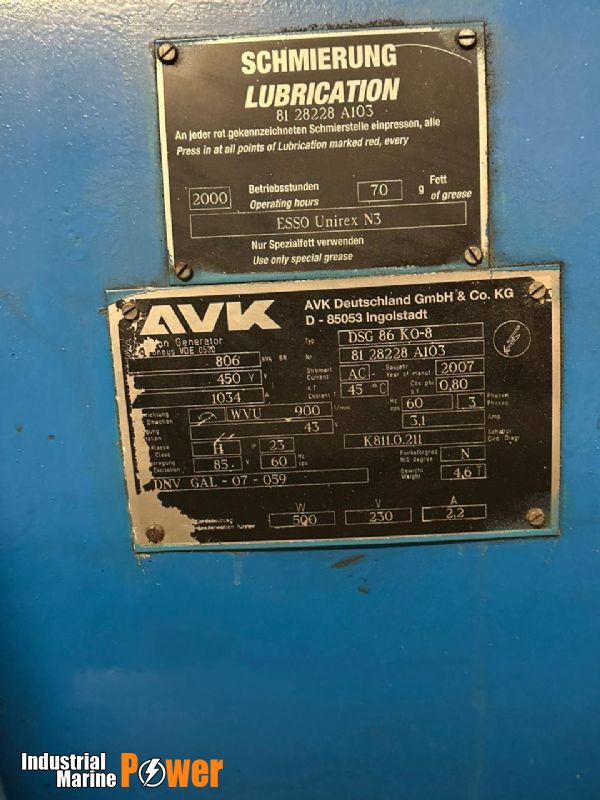
| Generator: | DSG 86 K0/8 | Poles: | 8 | Standards: IEC 60034,DNVGL | |
| Rated power: | 806 kVA | 645 kWe | 681 kWm | ||
| Power factor: | 0.80 | ||||
| Power at pf 1,0 | 654 kVA | 654 kWe | 681 kWm | ||
| Rated voltage: | 0.45 kV | ||||
| Speed: | 900 1/min | ||||
| Frequency: | 60 Hz | Voltage range / frequency range: | |||
| Rated current: | 1034.1 A | Operating Voltage Range+6% / -10% and Operating Frequency Range:+/-5% | |||
| Winding pitch: | ca. 5/6 | ||||
| Insulation class: | Stator: Class H | Rotor: Class H | Temperature rise: | F | |
| Ambient temperature: | 45 ° C | Environment: Standard environment | |||
| Site altitude: | 0 m | ||||
| Enclosure: | IP 23 + Solas | Filter: | Filter at airinlet | ||
| Cooling: | IC 01 - Open-circuit ventilation | ||||
| Coolant: | Ambient Air | Temperature Coolant: | 45 ° C | Temperature Air inlet generator: | 45 ° C |
| Cooling air vol.: | 2.0 m³/s | Cooling water quantity: | n/a | ||
| Moment of inertia(I): | 72 kgm² | Weight: | 3300 Kg | Losses (environment): Losses (cooling): | 36 kW n/a |
| Connections and regulators: | |
| Wires: | 4 terminals, starpoint connected in terminal box |
| Operation mode: | Island mode with different generators in parallel |
| Regulators: | |
| Voltage regulator: | DECS 100 |
| Electrical data: (acc. IEC) | |||||||||||||
| Efficiencies: | 110% | 100% | 75% | 50% | 25% | ||||||||
| Power factor 0.8 | 94,45 | 94,71 | 94,56 | 93,62 | 91,44 | ||||||||
| Power factor 0.9 | 95,14 | 95,37 | 95,05 | 93,96 | 91,72 | ||||||||
| Power factor 1.0 | 95,83 | 96,03 | 95,54 | 94,3 | 92 | ||||||||
| Reactances and timeconstants | |||||||||||||
| unsaturated | saturated | unsaturated | saturated | ||||||||||
| xd | 1.57 | 1.42 | p.u. | xq | 0.79 | 0.77 | p.u. | Td0' | 1.7 | s | Td0'' | 0.02331 | s |
| xd' | 0.250 | 0.250 | p.u. | xq' | 0.79 | 0.77 | p.u. | Td' | 0.27 | s | Tq0' | 0.26 | s |
| xd'' | 0.154 | 0.140 | p.u. | xq'' | 0.154 | 0.154 | p.u. | Td'' | 0.013 | s | Tq0'' | 0.13338 | s |
| x2 | 0.163 | 0.148 | p.u. | x0 | 0.046 | 0.042 | p.u. | Ta | 0.036 | s | Tq' | 0.26 | s |
| x1s | n.a. | 0.084 | p.u. | Tq'' | 0.026 | s | |||||||
| Short circuit ratiosaturated: 0.71 | Base Impedance (Zn) 0.251Ohm | ||||||||||||
| Short circuit data: | |||
| Initial short circuitcurrent (3-phase): | Ik'' | 7386 A | |
| Max. peak current (3-phase): | IS | 18802 A | |
| Sustained short circuit current: | Ik | 3102 A | Minimum 3 x rated current for max.10 s |
| Initial shortcircuit torque: | Mk2 | 79.4 kNm | |
| Mk3 | 47.6 kNm | ||
| Max. faulty synchron moment: | Mf | 170.7 kNm | |
| Rated kVA torque: | MSN | 8.55 kNm | |
| Rated torque | MN | 6.84 kNm | |
| Shaft torque | MSh | 7.22 kNm | |
| Load application: | |
max. load application: 490 kVA(corresponds to 60.8 % from 806 kVA) for Power factor 0.4 15% transient voltage drop | Power: 806 kVA Power factor: 0.8 transient voltagedrop: -20 % |
| Remarks: WD1977 | |
Preliminary values.For exact valuesplease see valid mechanical arrangement drawing.
1 | |||||||
| 2 | Application / Project: | Alternator type: | DSG 86 K0/8 | ||||
| 3 | CGT quotation no.: | 1-863-0000127-1 009572023 | Quantity: | 1 | |||
| 4 | Factory Projectno.: | ||||||
| 5 | Customer Orderno.: | Mode of operation: | Marine | ||||
| 6 | Delivery Date: | ||||||
| 7.1 | Order Type: | ||||||
| 7.2 | Reference: | ||||||
| 7.3 | Valid drawingat order entry: | ||||||
| 8 | Marine / Ship operation: | ||||||
| 9 | Shipyard.: | ||||||
| 10 | New building no.: | ||||||
| 11 | Type of vessel: | ||||||
| 12 | Construction acc.to classification society: | IEC 60034; DNVGL | |||||
| 13 | Inspection acc.to classification society: | ||||||
| 14 | Supply Type: | ||||||
| 15 | Prime mover: | ||||||
| 16 | |||||||
17 | Rated data | Rules, Standards | |||||
| 18 | Output: | 806 kVA | Standards: | IEC 60034; DNVGL | |||
| 19 | P.F. Cos Phi: | 0.80 | R.I.S. Degree: | VDE 0875 N | |||
| 20 | Voltage: | 0.45 kV | Insulation class: | Class H | |||
| 21 | Current: | 1034.1 A | Temperature rise: | F | |||
| 22 | Frequency: | 60 Hz | Ambient temperature: | 45 ° C | |||
| 23 | Speed: | 900 1/min | Altitude at site: | 0 m | |||
24 | Technical data | ||||||
| 27 | Efficiency: | see technical data sheet attached | |||||
| 28 | Rated load at cos phi= 0.8: | 94.82 | |||||
| 29 | Rated load at cos phi = 1: | 95.94 | |||||
| 30 | Efficiency tolerance: | acc. to VDE 0530,EN 60034 | |||||
| 31 | Reactances, timeconstants: | see technical data sheet attached | |||||
| 32 | Overspeed: | 1.25 x ratedspeed for 2 min | |||||
| 33 | Operating voltage range: | Operating Voltage Range +6% / -10% and Operating Frequency Range: +5% +/- 10% at no loadfor synchronisation, shortterm operation only | |||||
| 34 | Operating frequency range: | view line 33 | |||||
| 35 | Parallel operation: | Island modewith different generators in parallel | |||||
| 35a | Grid Code | Continuous mode S1/Base mode | |||||
| 35b | Mode of operation | Operating Voltage Range+6% / -10% and Operating Frequency Range: +5% | |||||
| 36 | Overload capability: | 10 % for 1 h every12 hours or 50 % for 30 sec. | |||||
| 37 | 3-phas. sustained short circuit current: | 3 x rated currentfor max. 10 sec. | |||||
| 40 | Start up conditions | ||||||
| 47 | Winding pitch: | ca. 5/6 | |||||
| 51 | Additiional loadon bearing/Shaft end | ||||||
| 53 | Design details, general
| ||||||
| ||||||
| 54 | Design form: | B16 / IM 130× IM 1305 | ||||
| 55 | AvK project drawing: | TBC after technically cleanorder placement | ||||
| 57 | Center height: | Must be confirmed at Order entry | ||||
| 58 | Flange bellhousing: | SAE adaptornot included | ||||
| 59 | Type of primemover / Manufacturer and name of prime mover: | Diesel engine/ 645W4L20 | ||||
| 61 | Mounting on Vibracon elements | |||||
| 62 | Shaft end / -flange (DE): | Flange | ||||
| 63 | Rotation facing DE: | counterclockwise | ||||
| 64 | Surface treatment: | Basic painting RAL 6011, Standard impregnation acc. to CGT standard | ||||
| 65 | Dynamic balancing: | Without Key | ||||
| 68 | Coupling assembly drawing | |||||
| 70 | Enclosure protection , Cooling type | |||||
| 71 | Enclosure alternator: | IP 23 + Solas | ||||
| 72 | Enclosure terminal box: | IP54 | ||||
| 73 | Cooling type: | IC 01 - Open-circuit ventilation | ||||
| 74 | Air filterat air inlet: | Filter at air inlet | ||||
| 75 | Filter control: | |||||
| 77 | Coolant: | Ambient Air | ||||
| 94 | Shipping | Delivery of cooler possibly dismounted. Clarification during transport organization before dispatch. | ||||
| 98 | Bearing arrangement + Lubrication | |||||
| 99 | Bearing Design: | Anti-Friction bearing | ||||
| 100 | Calculated Lifetime: | about 20.000operating hours | ||||
| 101 | Protection againstshaft currents / earthing brush | DE Side: Not insulated Earthing brush - rotor | NDE Side: Bearing insulated | |||
| 104 | Details of oilsupply | |||||
| 113 | Inclination | designed for 5°/7,5° static/dynamic | ||||
116 |
Terminal box + Accessories, Currenttransformers | |||||
| 117 | Location mainterminal box (seenon DE): | Standard terminal box; top | ||||
| 119 | Cable entry: | Cable entryright | ||||
| 121 | Cable glandplate: | Undrilled glandplate aluminium | ||||
| 122 | Details, quantity + diameter of cables: | Each phase:Cable qty. unknown; Type unknown; ODM unknown N point: Cable qty. unknown; Type unknown; ODM unknown | ||||
| 123 | Star point arrangement: | 4 terminals, starpoint connected in terminal box | ||||
| 124 | Location aux. terminal box (seen on DE): | top | ||||
| 126 | Supplier of CT's: | Transformers supplied by CGT Transformers installed by CGT | ||||
| 127 | Current transformers, starpoint side | Core 1 | Core 2 | Core 3 | ||
| 128 | - Primarycurrent: | 1250 A | ||||
| 129 | - Secondary current: | 5 A | ||||
| 130 | - Class: | 10P10 | ||||
| 131 | - Burden: | 15 VA | ||||
| 132 | - Standard test reports: | Not applicable | ||||
| 139 | Terminal marking for Direction of rotation | IEC 60034,part 8:2007 | ||||
| 141 | Voltage regulation system | |||||
| 142 | Voltage regulator: | DECS 100 Operational features code:B11 | ||||
| 148 | Power supplyof voltage regulator:: | Aux. winding | ||||
| 149 | Regulator location: | in auxiliary terminal box | ||||
| 154 | Instrumentation | |||||
| 155 | Temperature detection stator windings: | 6 PT100 | ||||
| 156 | Bearing temperature detection NDE-side: | Single PT100 | ||||
| 157 | Bearing temperature detection DE-side: | Single PT100 | ||||
| 159 | PT 100 design / connection: | Terminal connection for 3 wires | ||||
| 162 | Anti-condensation heater built-in: | Supply voltage 230 V, 1-phase, AC/DC Power required 500 W | ||||
168 |
Works Tests | |||||
| |||||
| 169 | CGT standard Test: | first generator: Standard Test acc.to AvK Specification CGTR-SP- 0316; all other generators (if applicable): only Repeat Test | |||
| 170 | Additional tests: | not applicable | |||
| 171 | Works testwitnessed by client: | not applicable | |||
| 174 | Documentation / Dates: | ||||
| 175 | Dimensional drawing: | ca. 4 weeks afterplacement of order | |||
| 177 | Shaft drawing with moment of inertia: | ca. 4 weeks afterplacement of order | |||
| 178 | Circuit Diagram | about 6 weeks afterplacement of order | |||
| 179 | Drawings as DXF-File | No | |||
| 180 | Operating instructions, Sparepart lists: | 2 weeks afteralternator delivery | |||
| 181 | Test reportsand Certificates: | 2 weeksafter alternator delivery | |||
| 183 | Language of documentation: | 1 x English | |||
| 184 | Printed Manual | ||||
| 202 | Additional details | ||||
| 203 | Voltage matching: For Decs 100 and 200the ratio of the sensingVTs for generator and busbar voltage can be different. The customer must ensure the heat transfer out of the machinery room. Alternator is designed for inclinations of: 5°/7,5° Fore-and-Aft & 15°/22,5° Athwartships (stat./dyn.). The altenatorshaft will be installed in parallel to the ships centerline. Please contact the factory if alternator shouldbe installed in athwarts direction. Cross Current Compensation (CCC): It must be ensured thatCCC is de-activated when the mode of regulation is changed from"AVR-mode" into "PF/VAR-mode". | ||||
Best regards,
Ibrahim Elyan
We use cookies to improve your experience. By continuing to use our site, you accept our Cookies, Privacy Policy,Terms and Conditions. Close X